
Add nodes
Adding a node, whether compute, head, login, storage, or anything in between, can
Command line
cv-conf -a node.<name>[xx-yy]This will drop you into a VIM editor for a YAML format. All details are given in the section “VALID PROPERTIES” at the bottom.
Nodes can also be added with common fields or configuration items already added with a template. To see a list of available templates:
# cv-conf -ta
monitoring_rule.appliance-diskspacelow.yml
monitoring_rule.cluster-mces-errors.yml
monitoring_rule.cluster-nodes-offline.yml
monitoring_rule.cluster-version.yml
monitoring_rule.disk-percent.yml
monitoring_rule.hw-raid-degraded.yml
monitoring_rule.infiniband-down.yml
monitoring_rule.sw-raid-degraded.yml
monitoring_rule.systemd-unit-offline.yml
monitoring_rule.zpool-degraded.yml
node.01-compute-node.yml
node.10-login-node-external-nfs.yml
node.11-login-node-internal-nfs.yml
node.15-login-nodes-existing-head.yml
node.20-head-no-appliance.yml
node.30-storage.yml
pdu.eaton-0U-g4-bottom.yml
pdu.eaton-0U-g4-top.yml
To add a node from template:
cv-conf -a node.<name>[xx-yy] -t <template>Example
cv-conf -a node.node[01-10] -t node.01-compute-node.ymlThis will open a YAML formatted file in a VIM editor to review, at the top of which important fields to are listed to review and configure as needed.
Graphical web
Unlike the command line option, the graphical web option will guide you through the details of set-up.
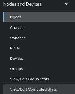
In the menu, select “Nodes and Devices”
Select Nodes
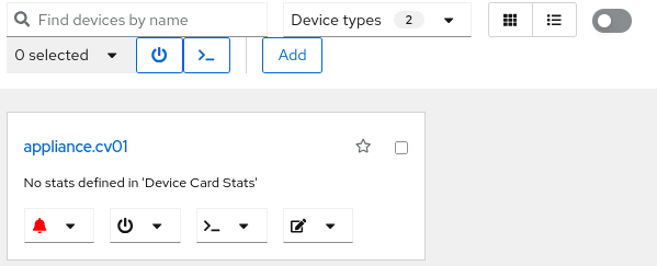
The appliance will be listed along with any other existing nodes. Click on “Add”.
Select a Template from the dropdown and give the node(s) a name. Click “Add”.
If adding multiple nodes at once in a range (e.g.: node00 through node10) then the nodes can be specified as node[00-10]
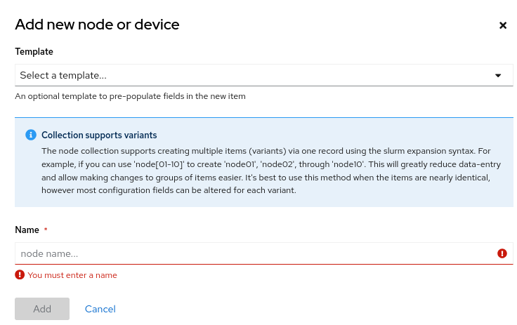
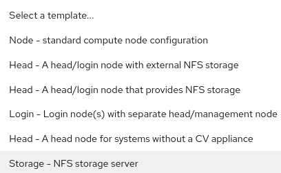
Dropdown list for selecting a node template
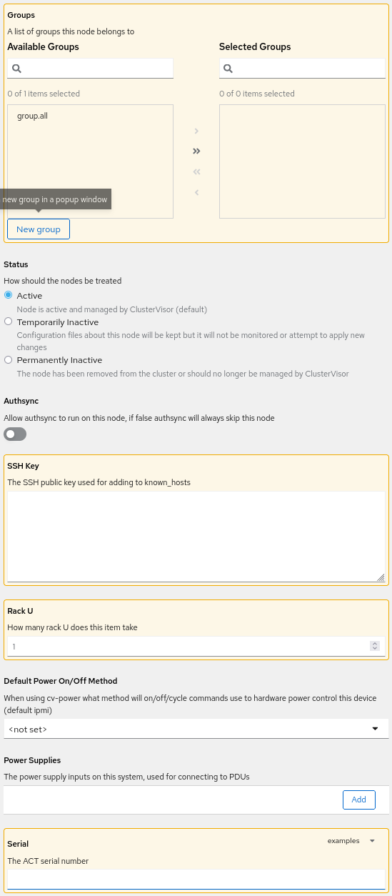
Each section that needs attention is listed with a yellow warning symbol with an exclamation point. Each section should be reviewed but these sections need attention where other sections the default values can be changed later as needed.
General
Select which groups in the Available Groups you want these nodes to be in then click the arrow into “Selected Groups”. If no acceptable group is listed, click “New group” - in the pop-up, give a name and click “Add” - In the next pop-up, other details can be given but none are required and all can be changed later; click “Save”. Then select the group and click the arrow.
The status should be “Active” but Inactive options can be selected as needed.
Authsync should remain disabled unless confirmed with ACT support it is needed and Authsync has been configured properly.
Add the node’s SSH Key, if you do not have one prepared at this time leave it blank. It can be added later. (This will add the node’s SSH public key to ~/.ssh/known_hosts across the cluster to prevent initial key accept prompts)
Change the number of Rack U the node takes up.
The Default Power On/Off Method can be set if you know. If left blank, it will defer to to the default of ipmi
The node’s Power Supplies can optionally be added. Adding the power supplies will allow the mapping of nodes' power connections in the rack diagram and enable power controls via the rack PDU (if PDU is a managed PDU).
Add the node’s ACT-provided Serial Number.
Provisioner / Cloner
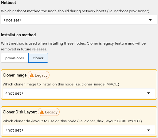
There are two methods for sending images to be provisioned to nodes: Cloner (legacy) and Provisioner (new).
Cloner is the legacy method for pre-2.x ClusterVisor. It should not be used for new 2.x installations and Provisioner should be used instead.
Cloner
Netboot should be set to “netboot.provisioner”.
Select “cloner” as the Installation method.
Cloner Image should be the image for the node (see Add an image if the appropriate image is not listed).
Cloner Disk Layout has a list of pre-populated disk layout options based on the disk type and quantity in the system – i.e., cloner_disk_layout.uefi-single, uefi-dual-mirror-nvme, legacy-single, etc. Select the appropriate layout in order for Cloner to identify the disk(s) to partition and RAID (if applicable).
Provisioner
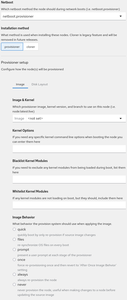
Set Netboot to netboot.provisioner to boot node into Provisioner on the next boot.
Select “provisioner” as the Installation method.
In the “Image” tab select an image from the “Image & Kernel” drop down. This will update the page and display additional drop downs for Branch and Kernel. These additional options are useful but are not discussed in this section.
“Kernel Options”, “Blacklist Kernel Modules”, and “Whitelist Kernel Modules” can be left empty unless you know kernel options or modules you know you need to specify.
Select an Image Behavior - Most of the time “quick” is preferred but all options should be reviewed for the best option.
Note: Selecting “Once” will bring up addition options to set the “After Once Image Behavior” - which behavior the provisioner system should use on subsequent boots
DO NOT CLICK SAVE YET - continue to “Disk Layout” section first!
Scroll back to the to top of “Provisioner setup” and click on the “Disk Layout” tab.
If node is diskless skip the remaining fields and jump to “Stateless Filesystem”
A “Disk Layout Behavior” must be selected for Provisioner to know when or how to apply the disk layout to the node(s). “Compare” is best to ensure balance of efficient boots and up-to-date disk layouts and images are maintained on nodes, but all should be reviewed.
“Disk Mode” has two options: Simple and Advanced. Advanced is not covered in this guide and should only be used in very customized situations. Leaving “Simple” selected is strongly recommended.
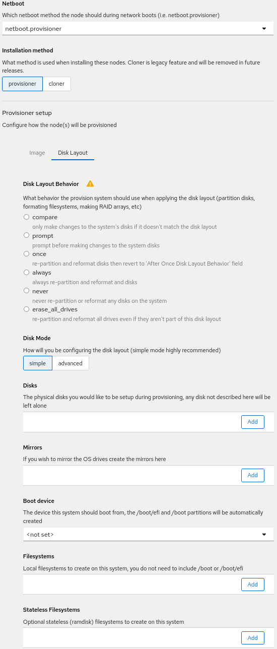
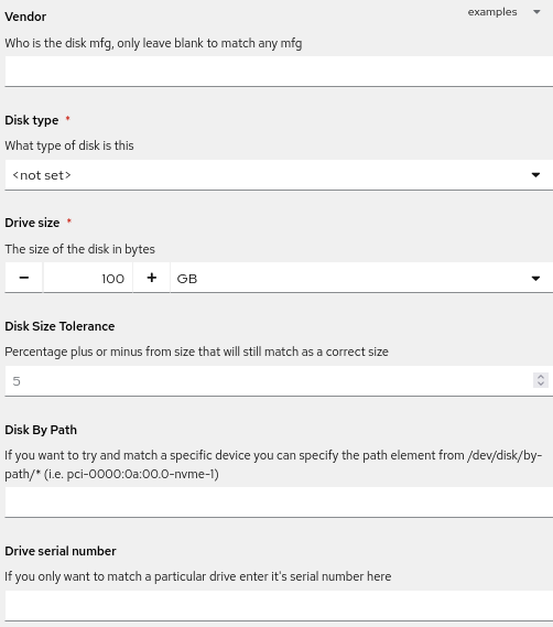
In the “Disk” field click “Add”. In the pop-up fill in the following values:
Note that there are helpful templates in the “examples” drop down.
Vendor - Must have a name
Disk type - Must be selected and match the disk type in the node(s)
Drive size - Should be close or less than actual size.
Disk Size Tolerance - A percentage of how close to the exact disk size to match. This is particularly helpful if the system sees the drive as a slightly different size than the drive is specified as. The default of 5 is usually sufficient.
Disk By Path - Useful for certain situations where there are many NVMe drives. This can be left blank.
Drive serial number - Useful to match exact drive; not all drives report this information.
When done, click “OK” and repeat to add more disks. Note, use the three-dot menu to “Duplicate” if adding more of the same type of disk to pre-load information. When done adding all disks continue to the next section.
“Mirrors” - If there are multiple drives that will be mirrored, add them here. The pop-up will allow selection of disks to be mirrored. Click “OK” when done.
“Boot device” - Select the drive which will have the boot information. This MUST be done before continuing to Filesystems.
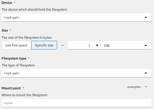
“Filesystems” - This is used to create partitions (LVM partitions if mirrors used) on the drive. Click “Add” on each drive or mirror listed. This will open a pop-up to configure and partition the filesystem.
Select the Device to install the filesystem
Specify a Size of the partition.
Select the Filesystem Type: XFS, EXT4, Swap. Note: Swap will remove the mount point selection.
Select the Mount Point. A quick selection of common options is available in the “examples” dropdown.
When complete select “OK”. Repeat this process for every filesystem partition.
“Stateless Filesystems” - If the node is intended to be “stateless” or “diskless”, with the image loaded into RAM only, click “Add”, then assign the ramdisk size and ramdisk mount point for the stateless filesystem.
When complete select “OK”. Repeat this process for every stateless filesystem partition.
Note: select the three-dot dropdown menu to “Duplicate” to pre-load the information when adding similar mount points.
Networking
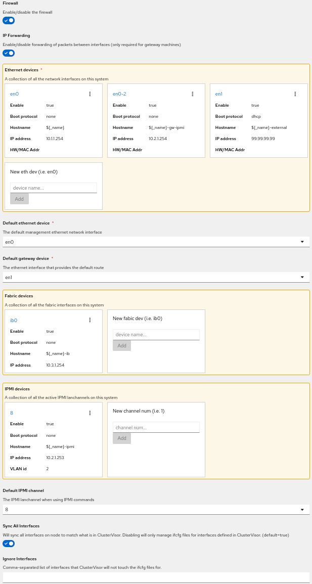
There are multiple sections that must be reviewed. Defaults are fine in most situations, but the IPMI password MUST be set before ClusterVisor will allow you to save.
The use of variables is used in multiple fields in this section and can be helpful to ease management of nodes and IPs without manual intervention and tracking. Variables are indicated by “${_<variable>}”. The two most used variables are “${_name}” and “${_index}”.
${_name} - retrieves the name of the system. Helpful
Firewall - Default for the template is generally best.
IP Forwarding - Default for the template is generally best.
Ethernet devices - These defaults are generally OK. However, verification of IP’s is always recommended. Click the interface name (eg: en0) and edit the “IP Address” field. Additionally, adding “HW/MAC Addr” is needed but can be done at another time /before/ booting the nodes.
Default ethernet device - should be selected as the primary private to the cluster network (eg: en0).
Default gateway device - select the correct interface; this will be different for different node types.
Fabric devices - verify IP and HW/MAC addresses.
IPMI devices - verify IP and HW/MAC addresses. Additionally, the IPMI password MUST be set. If the server does not use channel 8, click the three-dot drop down and select “Rename” (the channel is most likely 1).
Default IPMI channel - Must be selected. Majority of the time, there is only one option.
Sync All Interfaces - should be selected.
Ignore Interfaces - Leave blank unless an interface needs to be ignored.
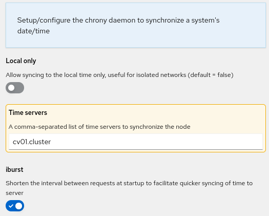
Time Server
Local only - default off
Time servers - cv01.cluster is default
iburst - default on
File System Mounts
Defaults will change depending on the node template type. Add additional mounts as needed. Use the three-dot menu at the end of a listed mount and select “Duplicate” to open a window pre-loaded that mount’s information to quickly add a new mount point. Be sure to update the new mount point accordingly.
For compute nodes, the default of “head:/opt” and “head:/home” are pre-populated. If using different hosts or hostnames for those directories, be sure to update accordingly.
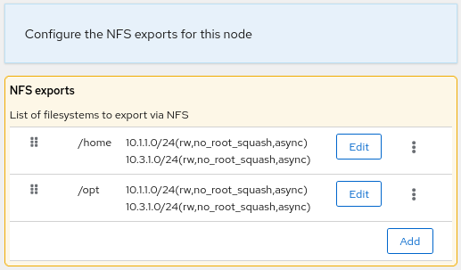
NFS Server
Defaults will change depending on the node template type. This may or may not be a required option. Defaults are sufficient most of the time. Use the three-dot menu at the end of an export line and select “Duplicate” to pre-load information into the new export’s fields. Be sure to update the new export’s fields accordingly.
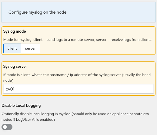
System Logging
Defaults are generally acceptable. Alter settings if needed.
Save
Finally, click “Save” and if there are no errors, the node will be added. If there are errors, make adjustments based on the red pop-up warning box.
At the top right corner of the page, the wrench icon will now be in a red box. Click the wrench, then click “Commit Changes”. This will bring up a pop-up with a list of nodes receiving changes and the plugins impacted by the changes. Click “Commit changes to nodes” to ensure all nodes in the cluster are aware of the new nodes.